A radiated immunity test asks a simple question: does the product keep working when it is hit by a radio signal of a given strength, for example 10 V/m? To answer it fairly, every part of the product's front face has to receive at least that strength. The antenna cannot promise that on its own. Reflections from the floor and walls, and the shape of the antenna's beam, make the field stronger in some places and weaker in others. Field uniformity calibration is how a laboratory proves, in advance, that the unevenness stays within agreed bounds.
- IEC 61000-4-3 calls the area the uniform field area: an imaginary upright square, normally 1.5 m by 1.5 m, starting 0.8 m above the floor, where the front of the product will stand during the test. The preferred distance from the antenna is 3 m.
- The square is marked out with 16 points, 0.5 m apart, and the field is measured at each of them with the chamber empty, at every test frequency from 80 MHz to 6 GHz.
- At each frequency, at least 12 of the 16 points must read between the required level and twice that level, for example between 18 V/m and 36 V/m. The standard writes this as 0 dB to +6 dB. The whole exercise is done twice: with the antenna horizontal and with it vertical.
The idea in plain words
Think of a photographer lighting a stage before a portrait. The subject will stand in one spot, and the photographer wants the light on the subject's face to be even. So before anyone steps on stage, the photographer walks a light meter across a grid of marks where the face will be and writes down each reading. If one side is much darker than the other, the lamps are moved until it is not.
A radiated immunity chamber does the same with radio waves. The "lamp" is the transmitting antenna, the "face" is the front of the product under test, and the light meter is a small field probe. The grid of marks is the uniform field area. It is not a physical object; it is a flat square of air, standing upright, exactly where the product's front face will be placed later.
Nothing is in the chamber while this is done, and that is deliberate. The calibration describes the room and the antenna, not the product. Once it passes, any product whose front face, including its cables, fits inside the square can be tested there.
The rule: twelve of sixteen, within a factor of two
Take a chamber calibrated at 18 V/m. At each frequency, the laboratory looks at the sixteen readings and asks whether at least twelve of them sit between 18 V/m and 36 V/m. The weakest of those twelve is brought to exactly 18 V/m; the strongest may be up to twice that, but no more. The standard writes the same rule as 0 dB to +6 dB, because 6 dB is simply a factor of two in field strength.
The band runs from the required level upwards, not evenly either side of it, and that choice matters. The standard accepts some over-testing, but it never accepts under-testing: every accepted point receives at least the level on the report, and none receives more than twice it.
Why 18 V/m?
The test level on a report, 10 V/m for example, is the strength of the plain, unmodulated signal. During the test that signal does not stay plain: it is amplitude-modulated by 80 % with a 1 kHz tone, which makes it rise and fall a thousand times a second. At the top of each rise the field is 1.8 times as strong as the plain signal, so a 10 V/m test briefly reaches the strength of an 18 V/m unmodulated field.
The chamber and the test equipment have to deliver those peaks cleanly, not just the average. The standard therefore asks for the field calibration to be done at no less than 1.8 times the test level. That is why a laboratory testing at 10 V/m calibrates its uniform field area at 18 V/m, and why the simulator below uses 18 V/m.
Four points of sixteen are allowed to fall outside, because real rooms have awkward spots: a corner near the floor where reflections gather, or an edge that the antenna's beam only just reaches. Which four may miss can change from one frequency to the next. If the product is small and the square is shrunk to its minimum of 0.5 m by 0.5 m, there are only four points and all four must pass.
The standard also records the field at 0.4 m above the floor, for products and cables that have to sit low. That reading is written into the calibration record for information; it does not decide whether the chamber passes.
Twice over: standing up and lying down
A radio wave has a direction of wiggle, called its polarisation. With the antenna mounted one way, the field swings side to side; turned through a quarter turn, it swings up and down. A product can be more sensitive to one than the other, so both are tested, and both have to be calibrated. The floor and walls treat the two differently, so the maps rarely look alike, and the simulator below shows only one of them. Across 80 MHz to 6 GHz in steps of 1 %, the full job comes to 435 frequencies, sixteen points and two polarisations: nearly 14,000 readings for one square.
See it change across frequency
The simulator below shows one polarisation, horizontal, with the chamber calibrated at 18 V/m. The upright view is the square as the antenna sees it: the colour runs from blue for a weak field through yellow to red for a strong one, and each of the sixteen points shows its reading in V/m. A solid line marks where the field reaches 36 V/m and dark stripes cover the area above it; a dashed line and light stripes mark where it drops below 18 V/m. A point left out carries an arrow showing which way it failed. The laid-flat view lays the same square on the floor and draws the field strength as height, so the field becomes a landscape of hills and hollows. The grey plane at 36 V/m is the limit: any point that pushes through it is left out, and so is any point that sinks below 18 V/m. Drag the slider to move through the band, drag the landscape to turn it, or click the chart underneath to jump to a frequency.
required36 V/m
limit
Simulated for illustration: a simple model of a 3 m chamber with absorber on the floor and walls, a broadband antenna to 1 GHz and a horn above it, horizontal polarisation. It is not the measured result of any particular chamber.
Why the picture changes with frequency
Field uniformity is not a property of any one part. It is what three things produce together: the chamber, whose size and shape decide where reflections come from; the absorbers, which decide how much of those reflections survive; and the antenna, which decides how the energy is spread across the square. Each of the three takes the lead in a different part of the band.
- At the low end, the chamber takes the lead. At 80 MHz a wavelength is almost 4 m, longer than the square is wide. Energy that bounces off the floor and walls arrives at the square alongside the direct wave, and the two add up in some places and cancel in others. The absorber on the floor between the antenna and the square is there to tame exactly this, and it works less well the lower the frequency.
- In the middle, the absorbers change jobs. Most chambers line their walls with ferrite tiles, which do the heavy lifting at low frequency, and foam cones, which take over higher up. Around the hand-over, the walls reflect a little more, and the map gets busier.
- At the top, the antenna takes over. A horn antenna concentrates its energy more tightly as the frequency rises, like a torch focused to a spot. The centre of the square stays bright while the corners fade. This is why the edge and corner points are usually the ones left out above a few gigahertz, and why the standard also offers, above 1 GHz, a method that checks the area in separate 0.5 m windows instead of one large square.
For a small number of frequencies below 1 GHz, the standard lets the band stretch from twice the required level to about three times it (from +6 dB to at most +10 dB), still never below the required level, for no more than 3 % of the frequencies, provided the wider figure is stated in the test report. At 18 V/m, that is up to about 57 V/m instead of 36 V/m. In a dispute, the factor-of-two rule takes precedence.
Uniformity also decides how much amplifier power you need. The test level is set at the weakest of the accepted points, so the drive is raised until that point reaches the required level. Where the field is even, the weakest point sits close to the rest and the amplifier has an easy job. Where the field is lumpy, or the corners fade, the drive has to rise until the weakest point is lifted to the level, and everything else in the square rises with it. The same test in a less even room asks more of the amplifier. That is why there is no single amplifier power that suits every scenario: it depends on the chamber, the absorbers and the antenna together, as well as on the test level, and it is sized for the combination, not read from a table.
A good solution is never one outstanding part. It is the know-how of how the four interact: the chamber, the absorbers, the antenna and the amplifier. Change one, and the other three have to be looked at again.
Because the result belongs to all four together, nobody can promise it for one of them alone. If someone offers to sell you just the antenna, just the absorbers, just the chamber or just the amplifier, and assures you it will do the job without having looked at the others, think twice: you are being sold a quarter of an answer. A horn with a beautiful beam on its datasheet can still fail in a room it has never met, and the best absorber in the world will not rescue an antenna that only lights the middle of the square. The only proof is a 16-point calibration with all four in place.
One example of a matched set
There is no single right combination. The chamber size, the antenna, the amplifiers and their power all follow from what you test and at what level: a laboratory testing consumer products at 3 V/m needs a very different set from one testing vehicle electronics or medical equipment at much higher levels. As one example, this is a set we would put forward for a product laboratory testing to IEC 61000-4-3 up to 6 GHz at moderate levels. Whatever the combination, the principle is the same: the chamber, the absorbers, the antenna and the amplifiers are chosen together, the software that runs the test is set up for that combination, and the 16-point calibration is done with all of them in place.
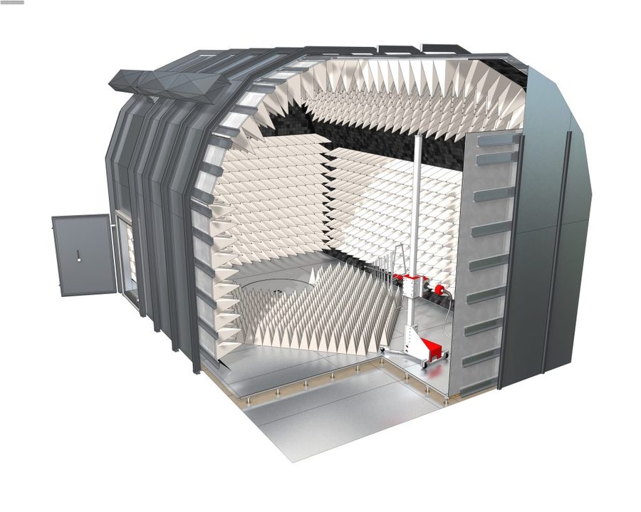

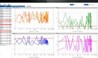
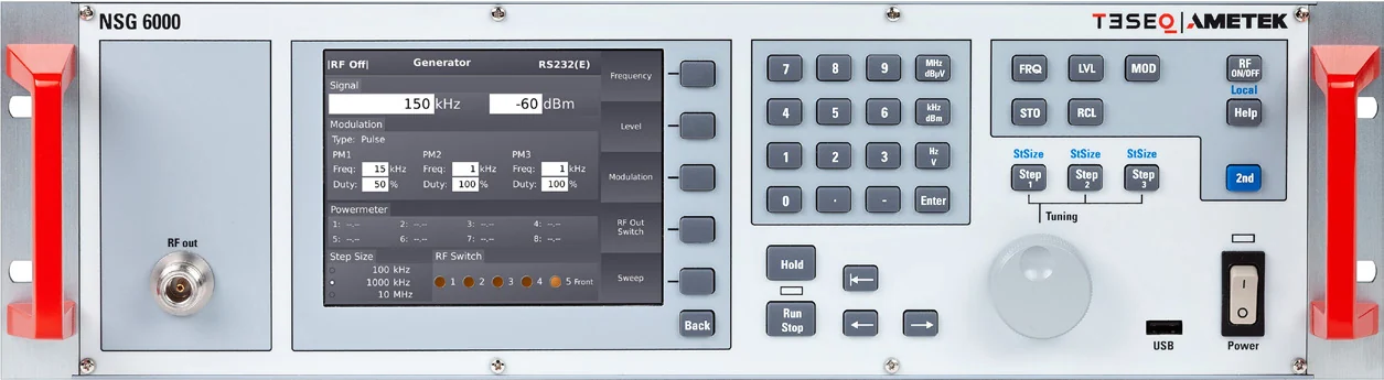
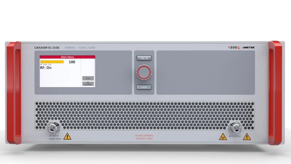
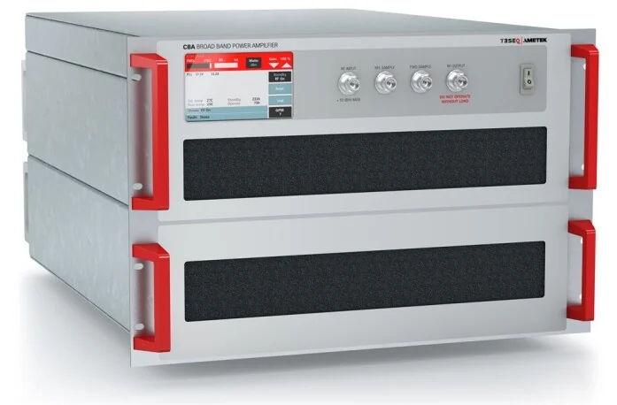
ICX Lab is the authorised distributor of AMETEK CTS products, of which Teseq and AR are brands, of Frankonia chambers and of Nexio BAT-EMC software. We size each set to the application and test level, then supply and install it as one, and verify it with the 16-point method. Quotations on request.
What the calibration gives you besides a pass
The sixteen readings are not only a verdict. At every frequency the calibration also records how hard the amplifier had to drive the antenna to produce the field. During the test, the laboratory uses that record to set the same field without a probe in the way. This is why the calibration only holds while the room stays exactly as it was: the same antenna in the same position, the same cables, the same absorber on the floor. Move any of them and the record no longer describes the room.
The standard expects the full calibration to be repeated every year, and whenever something in the room changes: absorber replaced, antenna moved, amplifier or cables exchanged. Before each batch of testing, the laboratory checks that the calibration still holds.
What to check in your own records
We offer 16-point field uniformity verification to IEC 61000-4-3 as a service outside our accredited scope. It is carried out on site with your own test system, driven by our field uniformity software, and it can be done in the same visit as the chamber's site validation. The laser-powered field probes the method depends on, such as the AR FL8000 series, are available through us as the authorised distributor of AMETEK CTS products, of which AR is one of the brands.
“A chain is only as strong as its weakest link.”
So is a uniform field. The test level is set at the weakest point, and the system is only as good as its weakest part.