IEC 61000-4-2:2025 cancels and replaces the 2008 edition, which had stood for seventeen years. Most of the test method is familiar. The generator specification and its calibration are where the standard moved, and a certificate issued against the old table does not answer the new one. This note sets the two editions side by side for the three changes that reach the calibration bench: the current waveform, the air discharge tip and the set-up.
- Waveform. Table 3 now has five parameters instead of four. A second peak current, the maximum between 10 ns and 40 ns, must sit within −20 % / +40 % of a nominal value. A 15 kV row has been added for the air discharge tip.
- Air discharge tip. The foreword's first listed change. The air tip is now calibrated: open-circuit voltage at the highest air discharge voltage used, and, if either tip contains any component, the current waveform in contact mode with the air tip mounted.
- Set-up. The calibration arrangement gains a reference ground plane of at least 1.5 m by 1.2 m bonded to the vertical plane, a toleranced target height of 1.0 m, rules for the return cable and the power supply, and an oscilloscope sampling rate of at least 8 GS/s. The current target drawing itself is unchanged.
1. The discharge current now has a second peak to meet
The 2008 edition defined the contact discharge current by four numbers at each level: the first peak, the rise time, and the current at 30 ns and 60 ns after the reference point. The 2025 edition keeps all four, with the same tolerances, and adds a fifth: the second peak current, defined as the maximum current in the window from 10 ns to 40 ns after the reference point. Its tolerance is asymmetric, −20 % to +40 %, and the nominal values follow the first peak at 60 %.
| Table 3 parameter | 2008 edition | 2025 edition |
|---|---|---|
| First peak current Ip1 | 7.5 A per 2 kV, ±15 % | Unchanged |
| Rise time tr, 10 % to 90 % | 0.8 ns, ±25 % | Unchanged |
| Second peak current Ip2 | Not specified | Maximum in 10 ns to 40 ns: 4.5, 9.0, 13.5, 18.0 A at 2, 4, 6, 8 kV, −20 % / +40 % |
| Current at 30 ns, I30 | 4 A per 2 kV, ±30 % | Unchanged |
| Current at 60 ns, I60 | 2 A per 2 kV, ±30 % | Unchanged |
| Levels in the table | 2, 4, 6, 8 kV contact | 2, 4, 6, 8 kV contact, plus a 15 kV row (56.3 A first peak, 33.8 A second peak, 30 A, 15 A) used for the air discharge tip |
| Contact output voltage, Table 2 | At least 1 kV to 8 kV | At least 2 kV to 8 kV |
The practical consequence is that a generator with a certificate to the 2008 table has never had its second peak measured. Most generators from the established makers will pass, because the second peak is a property of the 150 pF / 330 Ω network and the gun's construction, but "will pass" is not a calibration result. A certificate issued against the 2025 edition has a column the old one does not, and an assessor working to the new edition will look for it.
2. The air discharge tip is calibrated for the first time
The 2008 edition calibrated the generator in contact mode only. The air discharge tip was fitted for testing and its only requirement was the open-circuit voltage tolerance shared with the contact tip. Whatever the air tip did to the current waveform was never measured, and the foreword of the 2025 edition lists closing that gap as its first significant change.
Clause 6.3.1 now sets two cases. If the contact and air discharge tips are plain conductors with no active or passive electronic components inside them, the air discharge calibration is limited to measuring the open-circuit voltage at the air tip at the highest air discharge voltage used. If either tip contains components, which several current designs do, the current waveform is additionally measured to the same procedure as contact discharge, with the generator in contact mode but the air discharge tip mounted, at one of the levels in Table 1. That is why Table 3 gained a 15 kV row: the air discharge levels go to 15 kV, and the note allows the next lower air discharge level where a generator cannot be calibrated at 15 kV. Information on what is inside the tips comes from the manufacturer, and the certificate should state which case applied.
Two further requirements travel with it. The generator shall be powered for calibration the way it is powered for testing, so a gun used on both mains and battery needs both calibrations. And clause 7.2.2, the pre-test verification, now says both discharge tips shall be verified, with the small-spark observation given as one acceptable method.
3. The calibration set-up has a floor now
The 2008 arrangement was a vertical calibration plane with the target at least 0.6 m from any edge, the return cable connected 0.5 m below the target and pulled back into a triangle, and a note that the generator should stand on a tripod. The 2025 arrangement keeps the plane and adds a reference ground plane that the old figure did not have, with dimensions, heights and tolerances.
| Set-up item | 2008 edition, Annex B | 2025 edition, clause 6.3 |
|---|---|---|
| Vertical calibration plane | Target at least 0.6 m from any edge | Unchanged |
| Reference ground plane | Not specified | At least 1.5 m by 1.2 m, electrically connected to the vertical plane, large enough to cover the projection of the pulled-back return cable |
| Target height | Not specified; ground point 0.5 m below the target | Ground point 0.5 m ±0.05 m below the target and 0.5 m ±0.05 m above the ground plane, so the target sits 1.0 m up |
| Return cable | Pulled back at its midpoint into a triangle; not on the floor | Same triangle; shall not lie on the ground plane and shall not be held by an operator |
| Power supply | Generator powered as in use (note) | External supply placed on the ground plane, cable routed along the plane and the vertical plane; both mains and battery calibrated if both are used in testing |
| Generator support | Tripod or equivalent non-metallic support (note) | Tripod or equivalent non-conductive support, tip perpendicular to the plane (requirement) |
| Oscilloscope | At least 2 GHz analogue bandwidth | At least 2 GHz bandwidth and at least 8 GS/s sampling rate |
| High-voltage measurement | Meter for at least 15 kV, electrostatic voltmeter if needed | Resistive divider and voltmeter, ±1 % of reading, minimum input resistance as specified by the generator's manufacturer, or an electrostatic voltmeter of the same accuracy |
| Discharges recorded | Five per polarity at each level | Five per polarity at levels 1 to 4; at least one 8 kV positive waveform in the report |
| Current target, Annex B and C | Input impedance no more than 2.1 Ω; chain insertion loss ±0.5 dB to 1 GHz, ±1.2 dB to 4 GHz | Unchanged, including the example target drawing |
The ground plane matters more than its size suggests. The return cable's capacitance to whatever lies under it is part of the discharge circuit, and the 2008 figure left that to the room. Two laboratories with the same target and the same gun could measure different I30 values because one had a concrete floor and the other a raised metal one. Bonding a defined plane to the calibration plane, keeping the cable off it and fixing the target height removes that variable, and it is the reason the second-peak tolerance could be written at all.
What this means for a certificate
Generators built to the new edition
The three ESD simulators we supply and calibrate most often are specified by their manufacturers to the requirements of IEC 61000-4-2 Edition 3.0, including the second-peak tolerance and the air discharge tip calibration.
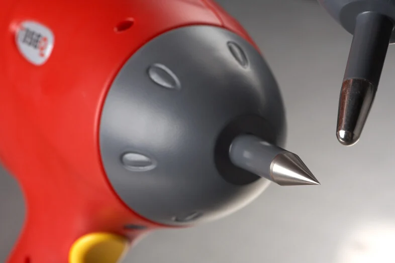
NSG 437
30 kV air and contact discharge, 150 pF / 330 Ω network as standard with more than 60 optional networks, interchangeable ball and point tips per IEC 61000-4-2, self-calibration at every start.
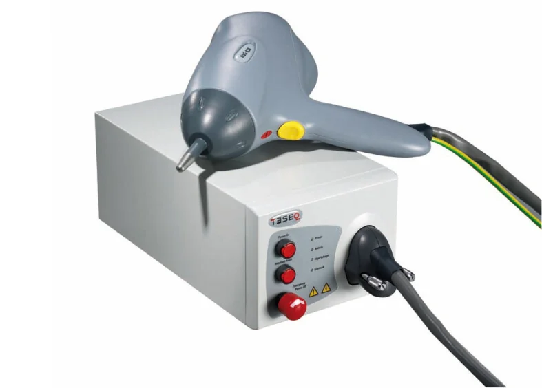
NSG 438
30 kV simulator with a base unit and a lightweight gun, colour touch display, voltage-hold, built-in bleed-off and a battery tested to 30,000 discharges at 30 kV.
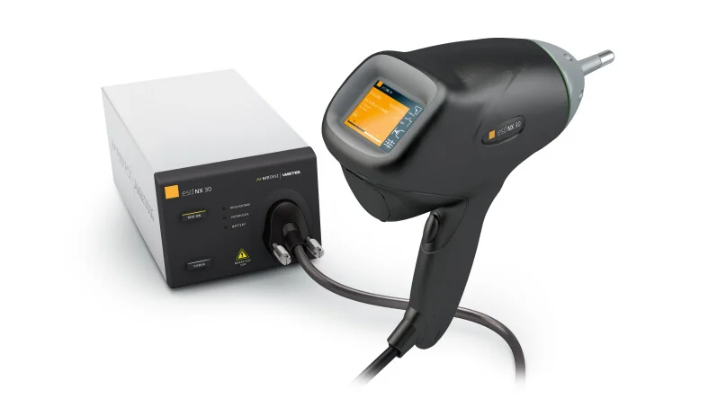
esd NX30
30 kV air and contact discharge with a battery base station, exchangeable R/C networks, switchable bleed-off, activity log and the esd.control library of standard routines.
Specifications from the AMETEK CTS datasheets dated July 2025. Quotations on request.
Both the 2008 and the 2025 editions of IEC 61000-4-2 are in the accredited scope we calibrate under, for the discharge current waveform parameters, the contact and air discharge voltage indication and the current target insertion loss, and the ESD simulator calibration guide lists the ranges. A calibration to the 2025 edition reports the five Table 3 parameters, the air discharge tip case that applied and the set-up used, and the certificate states the edition. If your generator's last certificate is to the 2008 edition, send it to us and we will tell you what the next one needs to add.