- EIRP and ERP are the same quantity against different references. EIRP compares the product with an isotropic radiator, ERP with a half-wave dipole, and the dipole already has 2.15 dB of gain: EIRP = ERP + 2.15 dB.
- The substitution method is a comparison, not an absolute measurement. That is its strength: the measurement antenna needs no absolute calibration, because it appears on both sides of the comparison. The calibrated antenna is the transmitting one, which is the reverse of a radiated emission test. ANSI C63.10-2013 gives its arithmetic in clause G.5.3.
- ETSI permits a characterised site instead. EN 300 328 and EN 301 893 say in clause C.4, and EN 300 220-1 in a note to clause C.5.3, that for a site with a fixed measurement antenna set-up and reproducible positioning of the product, correction values from a verified site calibration may be used instead.
EIRP and ERP: the same power, two yardsticks
Both quantities answer one question: how much power would a reference antenna need, to produce the same field in the direction the product radiates best? They differ only in which reference antenna is asked. ANSI C63.10-2013 puts it plainly in Annex G, the annex that collects the relationships between field strength, power, ERP and EIRP: the two are “similarly defined as the product of the power supplied to the antenna and the antenna gain”, the difference being that for ERP “the antenna gain is expressed relative to an ideal half-wave dipole antenna, whereas for EIRP, the antenna gain is expressed relative to an ideal (theoretical) isotropic antenna”. Equation (G.6) states the consequence in one line: EIRP = ERP + 2.15 dB.
Which one you are asked for depends on where you are selling and on the frequency. Under FCC rules the limit itself is often written as field strength or as conducted power with a gain cap, and EIRP is derived afterwards; the U-NII rules, by contrast, state e.i.r.p. directly. ETSI writes the limit in the radiated quantity from the start, and draws a clean line at 1 GHz. EN 300 328 puts it this way for emissions from a cabinet or an integral antenna: the limits are e.r.p. below 1 GHz and e.i.r.p. above 1 GHz. The same boundary decides how the substitution antenna must be calibrated: relative to a half-wave dipole below 1 GHz, relative to an isotropic radiator above it.
Why the air, and not the port
A conducted measurement at the antenna connector is faster, cheaper and more repeatable than anything done in a chamber. It is also the wrong quantity for an intentional radiator, for four reasons that the regulators state themselves.
- Gain is the point. Interference potential is power multiplied by gain in a direction. A port measurement needs the antenna gain supplied from somewhere, and the FCC warns that taking the maximum rated gain “can lead to conservative values when applied to spurious emissions on frequencies that are well removed from the frequency range over which the transmit antenna is presumed to have been optimized”. A spurious emission at 3 GHz does not care what the antenna was designed to do at 2.45 GHz.
- Often there is no port. FCC §15.203 pushes designs towards permanently attached antennas, and most radios today have an antenna printed on the board. ETSI's answer for those is a test fixture, and it is careful to say the fixture gives relative results only, for temperature and voltage variation, not an absolute level.
- The pair is what radiates. EN 300 328 applies its limit to “any combination of power level and intended antenna assembly”. Mismatch, the ground plane the antenna sits on and the case around it are all part of what leaves the product.
- Beamforming moves the target. With MIMO or a steered beam there is no single gain figure to add. ETSI asks for the product to be positioned, beamforming included, for maximum e.i.r.p. towards the measuring antenna, and that position to be recorded.
The substitution method, step by step
The method has two stages, and the second is what makes it absolute. In ETSI's wording, the first stage measures the product: the measurement antenna starts vertically polarised, the product is rotated through 360° in azimuth until the maximum is received, the measurement antenna is raised and lowered over its range until the maximum is found, that level is recorded, and the whole thing is repeated in horizontal polarisation. In a fully anechoic room the height scan is omitted; on an open site or a semi-anechoic room it is not.
Then the product comes out. A substitution antenna goes in its place, with its phase centre where the product's volume centre was. A signal generator is connected, set to the frequency being investigated, the mast is peaked again, and the generator is adjusted “until the same level is obtained as recorded from the UUT”. The radiated power is then the generator power, plus the gain of the substitution antenna, minus the cable loss — and the measurement is repeated in the other polarisation. ANSI C63.10-2013 states the same arithmetic in clause G.5.3, Equation (G.10): ERP or EIRP = PSG + GT − LC, where PSG is “the power setting of the signal generator that produces the same received power reading as the DUT”. It also carries a footnote worth knowing before you build a test plan around the method: “The signal (antenna) substitution technique is not accepted by some radio regulatory agencies for measurement of unlicensed devices.”
There is a reason this method has survived: it is a comparison, so most of the chain cancels. ETSI says so outright in its site description — the measurement antenna does not require an absolute calibration, because it receives both the product and the substitution antenna under the same geometry. The cable, the receiver and the room appear on both sides and drop out. What does not drop out is the gain of the substitution antenna.
It is worth being explicit about which antenna that is, because the arrangement is the reverse of the emission test most laboratories run every day. In a CISPR radiated emission measurement the calibrated item is the receive antenna: its antenna factor is what turns a receiver reading into a field strength, and its certificate is the one an assessor asks to see. In an EIRP or ERP substitution measurement the receive antenna carries no absolute weight at all — it only has to stay unchanged between the two stages — and the absolute reference moves to the transmit side, to the gain of the substitution antenna standing where the product stood. That gain enters the result dB for dB, and it is the figure that needs a calibration certificate with a date on it. A laboratory coming to radio testing from emissions work often has an impeccable certificate for the antenna that no longer needs one, and nothing for the antenna that does. The characterised site keeps the same arrangement: the reference antenna that measures the path is the calibrated item, and the whole receive side is folded into the factor.
What ETSI asks of that certificate is narrower than most people expect. Annex B.3.3 of EN 300 328, in wording repeated in EN 300 220-1 and EN 301 893, says the substitution antenna “shall be calibrated”, that below 1 GHz the calibration is relative to a half-wave dipole and above 1 GHz relative to an isotropic radiator, and that the antenna's return loss shall be taken into account when calculating the measurement uncertainty. It names no method. Where ETSI does point at one, it is through its test-site reports: TR 102 273 carries ANSI C63.5, “Calibration of Antennas”, among its references, and its worked uncertainty budgets give the gain of the substitution antenna a standard uncertainty of 0.5 dB while the gain of the measurement antenna contributes nothing at all — the same asymmetry, in numbers.
That leaves the method open, and a CISPR 16-1-6 calibration serves, which is convenient, because an accredited EMC antenna calibration usually is one. Three things have to be right on the certificate before the figure can be used this way.
- A free-space antenna factor, and only that. This is what the standard site method is built to produce, and it is worth knowing how. The site attenuation is measured over a ground plane at a defined geometry — typically 10 m separation, the transmit antenna at 2 m, horizontal polarisation, the receive antenna scanned over its height range — and the geometry is then removed analytically, by subtracting the theoretical site attenuation calculated for that same geometry from the two-ray model. The ground reflection is calculated out, not measured in. What survives is a property of the antenna alone, and that is the quantity that converts to a gain.
- The conversion, and the reference it lands on. For a passive antenna, G (dBi) = 20·log FMHz − AF − 29.79, and reciprocity makes a calibration done on the receive side valid in transmit use, provided nothing active sits in the antenna. Below 1 GHz, subtract a further 2.15 dB to reach the dBd figure ETSI asks for. Taking that step in the wrong direction is a 2.15 dB error, and it flatters the result.
- VSWR alongside the gain. In substitution the antenna is driven, not merely listened to, so the return loss ETSI wants in the budget has to arrive with the certificate. An antenna factor on its own does not satisfy that sentence.
Some laboratories ask their calibration supplier for an antenna factor measured by SSM at every geometry they test in — 3 m and 10 m, horizontal and vertical — and apply each one according to the configuration in use, reasoning that a number measured in the same geometry must be the more accurate one. The four numbers do come back different, but the difference is not the antenna. It is what the two-ray model could not capture at each geometry: coupling between the antenna and its image, worst in vertical polarisation and at low heights; mutual coupling between the two antennas at short separation; and the ground plane's own imperfection. Applying them per configuration writes site behaviour into the antenna term, where it is invisible afterwards, and where it is then counted a second time, because the site is already accounted for in the site validation and in the site-deviation term of the budget.
Where that coupling is real and large enough to matter, the calibration standards deal with it as a stated mutual-coupling correction applied to the free-space antenna factor, which keeps the antenna term and the site term separate and auditable. And 3 m vertical, the geometry the intuition trusts most, is the one with the largest calibration uncertainty of the four. For substitution work the division matters more, not less. Whether the antenna stands over the ground plane of a semi-anechoic room or on a non-conducting support in a fully anechoic room, whatever the floor contributes belongs to the path — where the site validation and the path factor already account for it — and not inside the antenna's own number.
And if you have ever run it
Then you already know what the procedure costs. It is not the thinking; it is the repetition. Every spurious frequency worth reporting needs the maximum found, the product lifted out, the substitution antenna set at the same point, the mast peaked again, the generator walked up or down until the reading matches, and then the same again in the other polarisation. Change band and the antennas change with it. A modern radio does not produce a handful of spurious frequencies; it produces a list. Move the slider to yours.
Nothing in that count is an exaggeration of the standard: the generator adjustments and the mast re-peaks are steps 3 and 4 of the substitution procedure, and the swaps are step 1. Nor does the count include the time the chamber door spends open, which is where positioning errors get in.
One thing is worth making explicit, because it decides the number you set. Every frequency has to be searched in both polarisations, since the reported figure is the larger of the two and you cannot know which that is without looking. But a substitution run is only needed where there is a level to match: if the emission sits at the noise floor in one polarisation, there is nothing to equalise against, and that observation is itself the justification for reporting the other one. So the count above is not the number of frequencies; it is the number of frequency-and-polarisation combinations that actually carry an emission worth reporting. For most radios that lands closer to twice the frequency count than to once, because a spurious does not have to share the polarisation of the fundamental, and cross-polar discrimination in a working chamber is often only 10 dB to 15 dB — so “only one polarisation” is frequently “one strong, one close to the limit”.
The sentence that offers another way
At the end of the same clause, after the six steps, ETSI adds a line that is easy to read past. EN 300 328 and EN 301 893 put it in clause C.4, and EN 300 220-1 as a note to clause C.5.3, in nearly identical words: for test sites with a fixed set-up of the measurement antenna and reproducible positioning of the product, correction values from a verified site calibration may be used instead.
That is the whole alternative, in one sentence. Characterise the path from the point where the product will stand to the receiver — once, with a known antenna, per band — and afterwards read the level and add the factor. EN 300 220-1 even spells out the reason in its receiver-side wording: one calibration measurement can be used for multiple tests.
ANSI C63.10-2013 has a related but distinctly different provision, and the two should not be confused. Its clause G.5.2 is headed “Direct calculation from the EUT power measured in a radiated test configuration [i.e., signal (antenna) substitution techniques not used]”, and gives EIRP = PR + LP, where PR is the received level corrected for measurement antenna gain, cable loss, attenuation and amplification, and LP is the theoretical free-space path loss, 20·log F + 20·log d − 27.5. That route trades the substitution stage for a calculated path. The ETSI sentence goes further: it lets you use a path you have measured and verified in your own room, which is the one that carries the reflections, the absorber and the cables you actually have.
Why it holds up technically
The substitution stage is not magic. It measures one thing: the loss from the place the product stands to the receiver input, at that frequency, in that polarisation, with that geometry. That path is a property of the room, the antenna and the geometry, not of the product. Measuring it with the product present and with a known antenna in the product's place gives the same number, because nothing in the path has changed between the two. This is the same logic that lets an antenna factor or a site attenuation be measured once and used afterwards, and it is exactly how the millimetre-wave world already works: 3GPP's over-the-air test ranges determine the composite loss of the whole path with a reference antenna in the quiet zone and then add it to every measured power, per polarisation and per signal path. The characterised site is the substitution method with its two stages decoupled in time.
The algebra is short enough to check by hand. Call the whole path from the product's position to the receiver input F, in dB: the spreading loss, the room, the gain of the measurement antenna, the cables, and any attenuator or preamplifier in between. Calibrate it once, by putting a reference antenna where the product will stand and driving it with a known level. The EIRP that antenna transmits is known, and the receiver tells you what arrives:
EIRPref = Pgen + Gref − LC → F = EIRPref − Pref
Afterwards, anything standing at that point is measured with one addition:
EIRPEUT = PEUT + F
Substitute the first line into the second and the equivalence is visible: EIRPEUT = PEUT − Pref + Pgen + Gref − LC. The substitution method is the special case where the generator is walked up or down until Pref = PEUT, so the first difference is zero by construction and what is left is exactly Equation (G.10), EIRP = PSG + GT − LC. The characterised site does not change the arithmetic. It performs that subtraction with numbers instead of with a generator dial, and it does it once instead of once per frequency. The single assumption is that F is the same on both occasions — which is what the conditions in the ETSI sentence are for.
The same number by both routes
A worked example, at 2.45 GHz in vertical polarisation, at 3 m in a fully anechoic room.
| Stage | Quantity | Value |
|---|---|---|
| Calibration | Generator level into the reference antenna, Pgen | −10.0 dBm |
| Cable loss on the transmit side, LC | 1.8 dB | |
| Reference antenna gain, Gref | 8.0 dBi | |
| EIRP actually transmitted, EIRPref | −3.8 dBm | |
| Level the receiver reads, Pref | −48.6 dBm | |
| Site factor, F = EIRPref − Pref | 44.8 dB | |
| Measurement | Maximised level from the product, PEUT | −22.3 dBm |
| EIRP = PEUT + F | 22.5 dBm, 178 mW | |
| The same result as ERP, for a limit written that way | 20.35 dBm | |
| Cross-check | Generator level that would reproduce −22.3 dBm, PSG | 16.3 dBm |
| EIRP = PSG + GT − LC | 22.5 dBm |
The two routes agree to the last decimal, because they are the same equation. And the 44.8 dB is not an invented figure: the theoretical free-space loss at 2.45 GHz over 3 m is 49.8 dB by the ANSI C63.10 expression, and a 7 dBi measurement antenna with 2 dB of receive cable brings the path to 44.8 dB. What the measured factor adds, over that calculation, is everything the formula cannot know — the room's own contribution, the antenna's real gain at that exact frequency, and the true state of the cabling on the day. That difference is the reason ETSI asks for a verified site calibration and not a spreadsheet.
The conditions in the sentence are the ones that keep that true, and they are not decorative.
- Fixed measurement antenna set-up. The path is only reusable while the geometry that produced it is unchanged: the same antenna, the same distance, the same height range, the same cables.
- Reproducible positioning of the product. The factor belongs to a point in space, and that point is not a free choice: the standard fixes the geometry — the support, the height the product sits at, the measurement distance, and the range over which the measurement antenna is scanned. Every laboratory has to place the product to that requirement whichever route it takes; manual substitution and a characterised chamber carry exactly the same obligation. The difference is only what the position is reproduced against. In the substitution method it is a swap made minutes earlier in the same session. On a characterised site it is a calibration made weeks or months earlier, so the marks on the turntable, the support itself and the written set-up have to hold over that interval.
There is an honest trade to note. In the substitution method the measurement antenna needs no absolute calibration, because it cancels. Take the substitution stage away and that cancellation goes with it: the path calibration becomes the load-bearing term, and its uncertainty is now part of every result. That is an argument for doing the calibration carefully and re-doing it when the room changes, not an argument against the method — the uncertainty budget simply moves from the bench to the calibration record, where it can be reviewed.
Two things the characterised site does not remove. The first is the search for the maximum. That is stage one of the method, carried out on the product itself and finished before a substitution antenna is ever wheeled in: the turntable still turns through 360°, both polarisations still have to be measured, and on an open site or in a semi-anechoic room the mast still scans. Manual substitution and a characterised chamber both start there, and neither makes it go away — what the characterised site replaces is stage two, the swap and the generator adjustment that follow. The second is that site validation is not site calibration. CISPR 16-1-4 validation tells you the room is fit to measure in; it does not give you the per-frequency path factor. The two live side by side in the records, and both have dates on them.
What to check in your records
Which of the two routes is right is a decision only the laboratory can make, and it is worth keeping open. A room that is characterised today still needs the substitution method the day a scheme or a regulator asks for it — the ANSI footnote above is a reminder that some agencies do — and a laboratory that substitutes today may characterise next year. The only thing that should not decide it is the software. The radio measurement module of Nexio BAT-EMC has both routes built in: a campaign can be run against a stored chamber calibration, or as a full antenna substitution, or one can be used to check the other. Either way the sequence itself is automated — the scan, the detection and re-measurement of each spurious, the turntable and the mast, the generator level walked up or down until the receiver matches, and the arithmetic that follows. What no automation reduces is what happens inside the chamber on the substitution route: the product still has to come out and the substitution antenna go into its place, and the substitution antenna still has to be changed when the band changes. Those are the steps that keep the door open, and they are the ones the counter above counts.
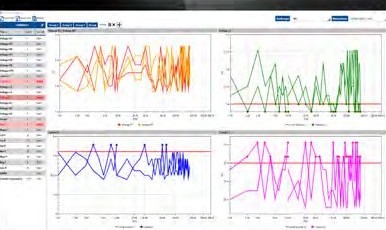
What we supply is the software that runs either route and leaves only the steps that genuinely have to be done by hand — and the room around it. ICX Lab is the authorised distributor of Nexio BAT-EMC software, and of the chambers, amplifiers and antennas that go with it, so the site that gets characterised is one we can also support after it has been characterised.
“Civilisation advances by extending the number of important operations which we can perform without thinking about them.”
A path measured once, verified, and applied afterwards is exactly that kind of operation. The thinking goes into the calibration; what follows is arithmetic.