Two questions arrive in the same week, and they sound the same. "Can I measure a single-phase product on the four-line LISN?" and "Can I use the M3 CDN on a class II appliance that only has live and neutral?" The first answer is yes, with the certificate you already hold. The second is no, and the level you set will be wrong by an amount you cannot see on the generator. Both answers come from one place: how each standard defines the impedance of the network.
- CISPR 16-1-2 defines a LISN's impedance per line, between each EUT terminal and reference ground. Each line is its own network, and the unused lines do not change it.
- IEC 61000-4-6 defines a CDN's impedance as a common-mode quantity, with all EUT terminals connected together. Remove a line and the impedance, and the division factor behind the test level, both change.
- A calibration certificate covers the configuration that was measured: per line for a LISN, all lines joined for a CDN.
The LISN: impedance is defined line by line
CISPR 16-1-2 specifies the V-network by the impedance between each EUT terminal and the reference ground, with the receiver port terminated in 50 Ω. The 50 Ω / 50 µH curve, and the ±20 % and ±11.5° tolerance, apply to every line on its own. That is also how the network is built: each line has its own 50 µH inductor, its own 50 Ω termination and its own tap to the receiver-port selector. A four-line network for three-phase supplies is four single-line networks in one case, sharing a mains filter and a switch.
So a single-phase product on L1 and N of a four-line network sees exactly the impedance a two-line network would present, and the certificate values for L1 and N are the ones that apply. The unused EUT terminals are simply left unconnected; there is no requirement to terminate or short them, because nothing in the definition depends on them. Three things still have to be right:
- The receiver-port selector is set to the line being measured, and each used line is measured in turn, as it would be on a two-line network.
- The certificate you rely on lists each line's impedance, division factor and isolation. A certificate that reports one line and calls it representative does not cover the others.
- The comparison is within the same network type. A 50 µH V-network used with fewer lines is still a 50 µH V-network. It does not become a 5 µH network for automotive supplies or a delta network, which are different definitions.
The CDN: impedance is defined for all lines together
IEC 61000-4-6 does not define a CDN's impedance line by line. Annex A specifies the common-mode impedance at the EUT port, measured with all the EUT terminals connected together and taken to the analyser through the 150 Ω to 50 Ω adapter: 150 Ω with a tolerance of ±20 Ω up to 26 MHz, wider above. The word "common mode" is the whole point. The disturbance is coupled onto every line at once, with the same amplitude and phase, and the 150 Ω is the impedance of that combined path.
The way an M-type CDN is built follows directly from the definition. The RF input reaches each line through its own coupling resistor, sized so that the resistors of all the lines in parallel make 100 Ω. Add the 50 Ω of the generator path and the EUT sees 150 Ω. The standard's own reference circuits give the values: 100 Ω for an M1, 200 Ω per line for an M2, 300 Ω per line for an M3.
Leave one line of an M3 unconnected and two resistors remain in parallel: 150 Ω plus the 50 Ω source, 200 Ω at the EUT port. The tolerance up to 26 MHz is 130 Ω to 170 Ω. The network is now outside the standard, and no setting on the generator brings it back. The same arithmetic applies to any M-type network used with fewer lines than it was built for:
| Network | Lines connected | Common-mode impedance at the EUT port | Against 150 Ω ± 20 Ω |
|---|---|---|---|
| M3 | L, N, PE | 150 Ω | As specified |
| M3 | L, N only | 200 Ω | Outside |
| M3 | One line only | 350 Ω | Outside |
| M2 | L, N | 150 Ω | As specified |
| M2 | One line only | 250 Ω | Outside |
Why the level is wrong, not just the impedance
The impedance is the visible half of the problem. The other half is the level. IEC 61000-4-6 sets the test level with the 150 Ω adapter on the EUT port, with all the terminals joined, and records the generator setting that produces the required voltage. That setting is then used for the product. It is valid only if the product's port presents the same arrangement the level was set with. With a line missing, the division factor from the RF input to the EUT terminals changes, so the recorded setting produces a different voltage at the product. The test report will say 3 V or 10 V. The product will have seen something else, and there is no reading on the bench that shows it.
That is also why the calibration certificate for a CDN applies to one configuration. The common-mode impedance and the division factor are measured with all the EUT terminals joined, because that is how the standard defines them. A certificate for an M3 says nothing about the same box used as an M2.
What to do with a two-wire product and a three-line network
Use a network built for two lines. An M2 network is the correct tool for a class II appliance, and an M1 for a single conductor. Where a laboratory tests both class I and class II products on the same bench, a switchable network such as the CDN M016 changes its internal resistor arrangement between the two-line and three-line configurations, so both are within tolerance, and it is calibrated in both settings. What does not work is connecting the unused PE terminal to the ground plane to "complete" the network. That puts a 300 Ω path from the RF input to ground that carries current into the plane instead of into the product, and the division factor is different again. The standard's arrangement is the only one the calibration covers.
Two definitions, two answers
| LISN, CISPR 16-1-2 | CDN, IEC 61000-4-6 | |
|---|---|---|
| Impedance is defined | Between each EUT terminal and reference ground, one line at a time | Between all EUT terminals joined together and reference ground, common mode |
| The other lines | Do not enter the definition; each has its own network | Are part of the definition; each carries one of the parallel coupling paths |
| Built as | Independent 50 µH / 50 Ω networks with a receiver-port selector | One coupling network whose per-line resistors are sized for the number of lines |
| Calibrated | Line by line: impedance, division factor and isolation per line | All terminals joined: common-mode impedance, division factor, decoupling |
| Using fewer lines | Valid. The used lines are unchanged and their certificate values apply | Not valid. Impedance and division factor both change, and the certificate does not cover it |
Before you connect fewer lines than the box has
One network for both configurations
The practical answer for a bench that sees class I and class II products is a network that changes its own resistor arrangement rather than an operator who leaves a line open. The Teseq CDN M016 does exactly that.
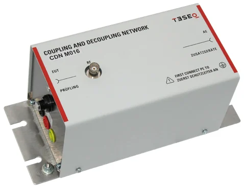
Teseq CDN M016, switchable M2 or M3
A single 16 A mains CDN with a switch that selects the two-line (L, N) or three-line (L, N, PE) configuration. In each position the internal coupling resistors are the ones the standard's reference circuit calls for, so the common-mode impedance at the EUT port stays at 150 Ω whether the product has a protective earth or not.
- Switchable M2 or M3: L and N, or L, N and PE
- 150 kHz to 230 MHz, 16 A, 4 mm safety banana sockets on the EUT and AE ports
- Common-mode impedance 150 Ω ±20 Ω to 24 MHz, then 150 Ω +60 / −45 Ω to 80 MHz and ±60 Ω to 230 MHz
- Voltage division factor 9.5 dB, +1.5 / −1 dB, from 150 kHz to 80 MHz
- 250 V line to ground and 433 V line to line AC, 400 V and 800 V DC
- M016S version adds the calibration adapter set: common-mode adapters for both configurations, the 100 Ω adapters and a 50 Ω termination
Each configuration is a separate calibration, and a level-setting file per configuration in the generator. The certificate names the setting it was measured in. Specifications from the AMETEK CTS CDN M series datasheet. Quotations on request.
On site, we calibrate LISNs line by line, so a network used with fewer lines is covered by the same certificate. CDNs are measured with the EUT terminals joined, in each configuration the network offers, and the certificate states which. The LISN and ISN and CDN guides list the parameters and ranges. If you are unsure whether a network on your bench is being used in the configuration it was calibrated in, send us the certificate and a photograph of the set-up.