Medical devices · IEC 60601-1-2 ed. 4.1

Proximity field immunity, without the tangle

Edition 4.1 tests medical devices against the transmitters used next to them: magnetic fields from 9 kHz to 13.56 MHz and radio fields up to 5.8 GHz. Two systems cover both. Low Frequency RF: the NSG 4070C-LFCP with its loop sets for the magnetic fields. High Frequency RF: the NSG 6000A with CBA amplifiers and the TEM horn for the radiated fields.

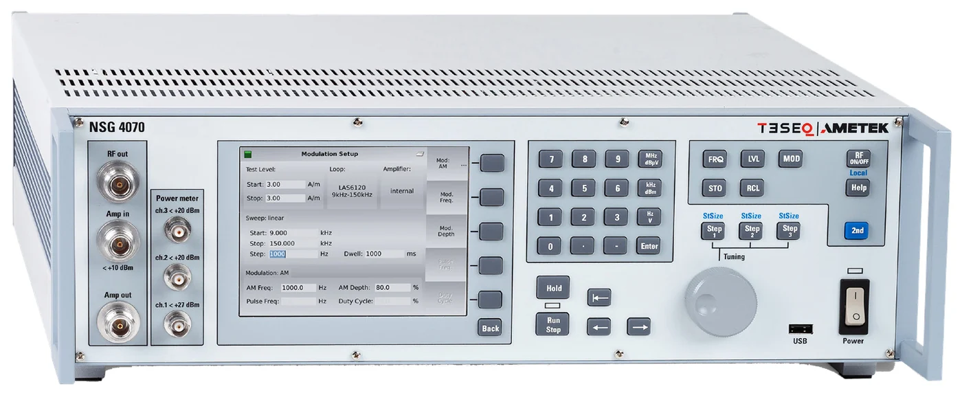
Teseq NSG 4070C-LFCP front panel showing the LAS 6120 test menuNSG 4070C-LFCP with the LAS 6120 test loaded on its own screen
Low Frequency RF · Proximity magnetic field

Generator and loops, made for each other

Each part is specified by Teseq for IEC 61000-4-39 and IEC 60601-1-2, so the level-setting distances, sensor correction factors and drive powers are already matched.

Teseq NSG 4070C-LFCP test system
Star product

NSG 4070C-LFCP

Signal generator, class A power amplifier, directional coupler, three power meters and EUT monitoring in one 19-inch unit.

  • Generator and power meters 4 kHz to 1 GHz
  • Internal amplifier 100 W, 9 kHz to 50 MHz
  • Menu-driven test and calibration on the 5.7-inch display, results to USB
  • Optical, analogue, digital and TTL EUT monitoring
  • LAN, USB and optical RS-232 remote control
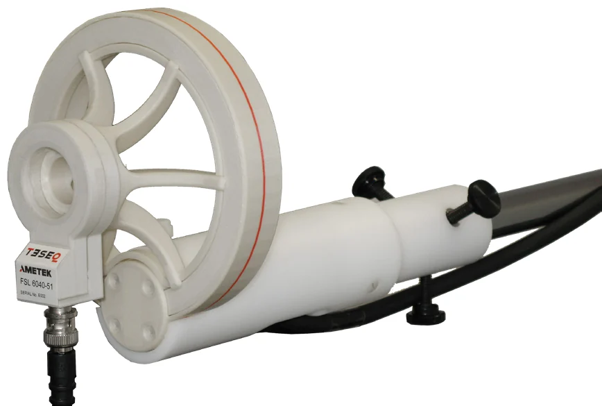
Teseq LAS 6120 radiating loop antenna with FSL 6040-51 field sensor loop
9 kHz to 150 kHz

LAS 6120 loop set

Radiating loop, field sensor loop, current probe and tripod fixture. The fixture holds the 50 mm test distance the standards require.

  • RLA 6120-20 radiating loop, 20 turns, 120 mm
  • FSL 6040-51 sensor loop with correction factor
  • CSP 9160A current probe for level verification
  • Also meets MIL-STD-461 RS101
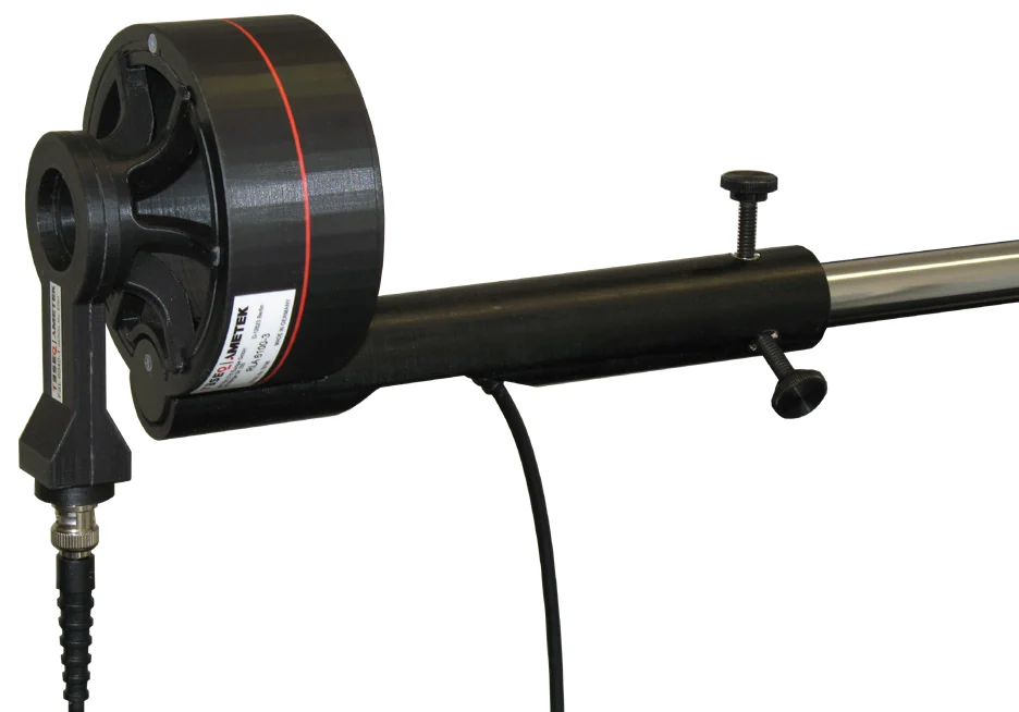
Teseq LAS 6100 radiating loop antenna RLA 6100-3
150 kHz to 30 MHz

LAS 6100 loop set

The higher-frequency loop for the same fixture, with the adaptor the 13.56 MHz medical test point needs.

  • RLA 6100-3 radiating loop, 3 turns, 100 mm
  • FSL 6040-1 sensor loop with correction factor
  • ANP 4039 adaptor for 7.5 A/m at 13.56 MHz
  • 80 mm radiation area panel and spacer
The pain point

A distributed set-up turns a 20-minute test into an afternoon

The proximity magnetic field test looks simple: a loop, a sensor and a level. Built from separate instruments, it is anything but.

Conventional: assembled from separate instruments

Signal generator, external amplifier, coupler, power meters and a PC, each with its own driver, cables and calibration.

PC and softwareSignal generatorExternal amplifierDirectional coupler Power meterPower meterLoop antennaEUT drivers for every box4 kHz to 1 GHzseparate calibrationforward and reverse forward powersensor loopplus sensor loopmedical device control and readback links: one per instrument
7boxes on the bench
5software drivers to keep working
3calibration certificates to track
  • Level setting runs through the PC: generator step, meter read, correct, repeat, at every frequency
  • Cable and coupler losses at 9 kHz and again at 13.56 MHz must be entered by hand
  • Sensor loop factors live in a spreadsheet, not in the instrument
  • A driver update or a licence lapse stops the test

Integrated: NSG 4070C-LFCP with the loop set

Generator, amplifier, coupler and the three power meters share one chassis, one firmware and one calibration.

NSG 4070C-LFCP Generator100 W amplifierCoupler3 power metersEUT monitoring Loop antennaLAS 6120 or 6100 EUTmedical device sensor loop back One menu: test level, loop, sweep, modulation, run
1box, plus the loop set
0drivers needed to run a test
1calibration for the whole chain
  • Level setting for a full range takes under a minute from the front panel, stored as a calibration file
  • Amplifier, coupler and meters are matched at the factory, so no loss tables
  • Loop and sensor names are selected in the menu with their factors already in place
  • The same unit runs IEC 61000-4-6 conducted immunity with a CDN
Our strengths · Low Frequency RF

Why we lead with the LFCP for magnetic proximity

Built for ed. 4.1, not adapted to it

IEC 61000-4-39 and IEC 60601-1-2 are the two standards on the datasheet. The 30 kHz, 134.2 kHz and 13.56 MHz test points are preset, including the pulse modulation each one calls for.

No laptop on the bench

The test is configured, calibrated and run from the instrument's own menu, with the results exported to a USB stick. Software is an option for automation, never a requirement.

The distance is built in

The loop fixtures hold the 50 mm spacing and the spacer sets the sensor position for level setting, so the geometry the standard draws is the geometry on the bench.

Two loops, one instrument

LAS 6120 and LAS 6100 share the fixture and the menu. Switching from 30 kHz to 13.56 MHz is a loop change, not a bench rebuild.

Not locked to one test

The same NSG 4070C runs conducted RF immunity to IEC 61000-4-6 with a CDN, so the instrument works every week, not only for the proximity test.

Supported and calibrated here

ICX Lab Services installs the system, trains the team and calibrates the loops and sensors on site under the accredited scope, so the laboratory stays in service.

High Frequency RF · Fields with the TEM horn

One generator, two amplifiers, one horn

The NSG 6000A routes its signal to the right amplifier through its own switch matrix and reads the power meters directly, so the 80 MHz to 6 GHz chain behaves as one instrument.

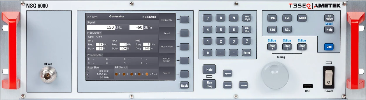
Teseq NSG 6000A radiated and conducted immunity test system
Star product

NSG 6000A

Signal generator, RF switch network, power meter interface and EUT monitoring in one 3U unit.

  • Generator 9 kHz to 6 GHz
  • Built-in switch network with five RF outputs, and SPDT or SP6T switches to combine amplifiers into one antenna path
  • Reads up to eight PMR 6003 or PMR 6006 power meters directly
  • Three pulse modulators for radar profiles
  • Four digital and one analogue EUT monitoring inputs, 14 control outputs
  • About 11 kg
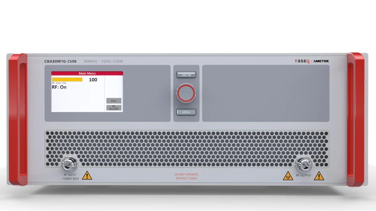
Teseq CBA80M1G E series solid-state amplifier
80 MHz to 1 GHz

CBA 80M1G E series

Single-band class A amplifiers built on the AR design, sized from bench to rack.

  • 100 W to 975 W at 1 dB compression
  • CBA80M1G-125E: 3U, about 16 kg, 100 W P1dB
  • Colour touch panel for monitoring and diagnostics
  • Ethernet, USB, RS-232, optical RS-232 and GPIB
  • Designed to pair with the CBA 4G, 6G and 8G series
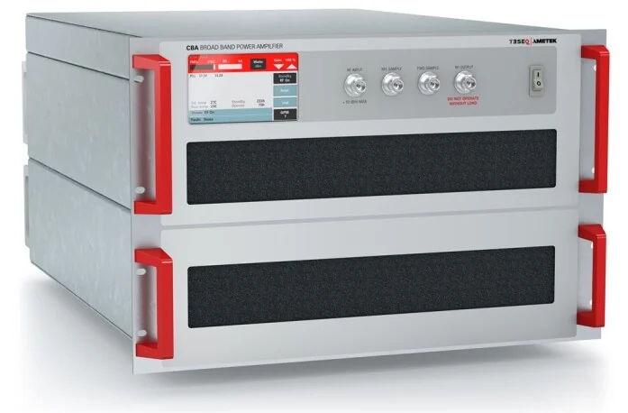
Teseq CBA6G-200D solid-state amplifier
0.8 GHz to 6 GHz

CBA 6G D series

Class A amplifiers from 30 W to 400 W that cover every transmitter band above 800 MHz in one box.

  • CBA6G-200D: 200 W P1dB, 7U, 50 kg
  • Built-in calibrated directional coupler for forward power
  • 100 percent mismatch tolerant, no foldback
  • Touch screen shows forward and reverse power
  • Ethernet, USB, RS-232 and GPIB, three-year warranty
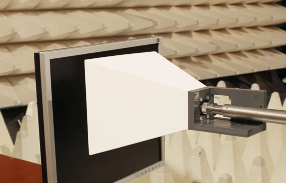
Teseq TEM horn in front of a monitor inside an anechoic chamber
380 MHz to 6 GHz

TEM horn for IEC 61000-4-39

One horn for the whole close-proximity RF range.

  • 600 MHz to 6 GHz, usable from 380 MHz
  • MNW 400 and MNW 460 matching networks for the TETRA 400, GMRS and FRS 460 bands
  • 15 W to 250 W for 300 V/m at 0.1 m
  • Field homogeneity 0 to minus 4 dB over 250 square centimetres, typical
  • 0.5 kg with fixture, camera thread
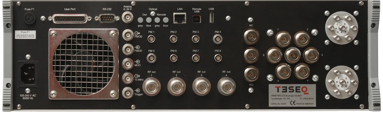
NSG 6000A rear panel with generator outputs, switch options and power meter inputs

The rear panel is the system

What a distributed bench spreads over a switch box, a power meter mainframe and a monitoring unit is on the back of the NSG 6000A.

  • Four generator outputs plus the front output, one per amplifier
  • Factory-fitted SPDT and SP6T switches, N or SMA, to bring two amplifiers to one antenna
  • Power meter inputs for four PMR heads, eight as an option
  • User port, analogue input and optical port for EUT monitoring
  • LAN, USB, RS-232 and optical remote control
The pain point

Two amplifiers, one antenna, and a bench full of boxes in between

Covering 80 MHz to 6 GHz needs two amplifiers. In a distributed set-up, everything that joins them is another box, another cable and another driver.

Conventional: generator, switch box, meter mainframe, monitor

The generator, the RF switch box, the power meter mainframe and the EUT monitor are separate purchases with separate remote interfaces.

PC and softwareSignal generatorRF switch box Amplifier 1Amplifier 2Combiner switch Power meter mainframeEUT monitor unitEUT drivers for every box9 kHz to 6 GHzseparate controller 80 MHz to 1 GHz0.8 to 6 GHzthen TEM horn two heads, GPIBown interfacemedical device seven control and readback links, four interface types
9boxes on the bench
7remote links to keep alive
4interface types, GPIB to LAN
  • The switch box and the meter mainframe are the two items that fail first and stop the whole chain
  • Every band change is a software handshake across three vendors' drivers
  • Forward power comes from one instrument, field level from another, and the PC reconciles them
  • EUT monitoring is a separate unit with its own cabling to the chamber

Integrated: NSG 6000A with CBA amplifiers and the TEM horn

Switching, power reading and EUT monitoring are inside the generator. The amplifiers and horn are the only other boxes.

NSG 6000A GeneratorRF switch matrixPower meter interface, 8 headsEUT monitoring one LAN link to the Nexio BAT-EMC software CBA 80M1G ECBA 6G DTEM hornEUT 80 MHz to 1 GHz0.8 to 6 GHzvia SPDT switchmedical device PMR heads read back into the generator
4boxes, generator to horn
1remote link for the whole system
0external switch or meter units
  • The switch matrix selects the amplifier per frequency, inside the generator
  • Up to eight PMR power meter heads plug straight into the rear panel and are read with the generator's own timing
  • EUT monitoring and the optical chamber link are on the same unit
  • Nexio BAT-EMC controls one instrument, and the amplifiers report through it
Our strengths · High Frequency RF

Why we lead with the NSG 6000A for the RF fields

The switch matrix is built in

Five RF outputs and factory-fitted SPDT or SP6T switches mean two amplifiers reach one antenna without an external switch box or its controller.

Power meters plug into the generator

Up to eight PMR 6003 or PMR 6006 heads connect directly. Forward, reverse and field-sensor readings arrive at the instrument that sets the level, with no mainframe in between.

Two amplifiers cover 80 MHz to 6 GHz

The CBA 80M1G E and CBA 6G D series are designed as a pair, with a common control interface and built-in couplers, so the hand-over at 1 GHz is a switch position.

Radar pulses ready

Three configurable pulse modulators from 1 microsecond to 200 seconds reproduce the pulse profiles that transmitter tests and automotive standards call for.

One horn for every band

From TETRA at 400 MHz to 5.8 GHz with a single TEM horn and two clip-on matching networks. No antenna change between the transmitter bands the standard lists.

Supported and calibrated here

ICX Lab Services installs the system, trains the team and calibrates the power meter heads, couplers and horn on site under the accredited scope.

Test coverage

Proximity field tests these two systems perform

Levels are those published in the standards and the Teseq datasheets. The remaining IEC 60601-1-2 immunity tests, such as ESD, burst, surge and dips, are covered by the compact NX7 and esd NX30 on the AMETEK page.

TestStandardRequirementEquipment
Low Frequency RF · Proximity magnetic field
Proximity magnetic field, 30 kHzIEC 60601-1-2 ed. 4.18 A/m, CWNSG 4070C-LFCP with LAS 6120
Proximity magnetic field, 134.2 kHzIEC 60601-1-2 ed. 4.165 A/m, pulse modulation 2.1 kHzNSG 4070C-LFCP with LAS 6120
Proximity magnetic field, 13.56 MHzIEC 60601-1-2 ed. 4.17.5 A/m, pulse modulation 50 kHzNSG 4070C-LFCP with LAS 6100 and ANP 4039
Magnetic field in close proximityIEC 61000-4-399 kHz to 150 kHz, 1 to 30 A/m, AM 1 kHzNSG 4070C-LFCP with LAS 6120
Magnetic field in close proximityIEC 61000-4-39150 kHz to 26 MHz, 0.1 to 3 A/m, pulse modulationNSG 4070C-LFCP with LAS 6100
Conducted RF immunityIEC 61000-4-63 V, 6 V in ISM bands, 150 kHz to 80 MHzNSG 4070C-LFCP with CDN M216 or M316
High Frequency RF · Radiated and proximity fields
Radiated field in close proximityIEC 61000-4-39380 MHz to 6 GHz, up to 300 V/m at 0.1 mNSG 6000A, CBA 80M1G E and CBA 6G D, TEM horn with MNW 400 and MNW 460
Proximity fields from RF wireless equipmentIEC 60601-1-2 ed. 4.1385 MHz to 5.8 GHz, up to 28 V/m at 0.3 mNSG 6000A, CBA 80M1G E and CBA 6G D, TEM horn or AR ATR26M6G antenna
Radiated RF immunityIEC 61000-4-310 V/m, 80 MHz to 2.7 GHzNSG 6000A, CBA 80M1G E and CBA 6G D, AR ATR26M6G antenna, PMR 6006 heads

Adding ed. 4.1 proximity tests to your laboratory?

Tell us which devices you test and what you already own. We configure the loop system, the RF system or both, size the amplifiers to your field levels and distances, and calibrate everything on site after delivery. Quotations on request.

Request a quotation   WhatsApp us

Tell us what you need to test

We reply within one working day with a quote or a plan.

Contact us