High-voltage DC power · ISO 21498-2, LV 123, CISPR 25, IEC 61000-4-x on DC ports

Ripple, emission and immunity on buses up to 1000 V DC

Chargers, DC-DC converters, inverters and battery systems are tested on their high-voltage bus, at operating current. Two systems cover that bus. HV ripple: the Ripple NX with the ISO 21498-2 artificial network. HV coupling: artificial networks and coupling networks rated for the bus, so emission and immunity tests run at voltage instead of derated.

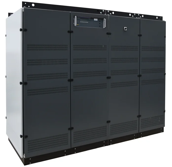
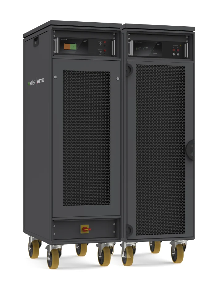
EM TEST Ripple NX high-power ripple generatorRipple NX: source and coupler racks, up to 1000 V and 1000 A DC
HV ripple · ISO 21498-2, LV 123, VW 80300, MBN 11123

Ripple injected at bus current, measured at the terminals

The Ripple NX puts a controlled AC ripple onto a live DC bus and measures it at the EUT with frequency-selective channels, so the level is closed-loop whatever the EUT's impedance does. The HV-AN 1u-500 gives the source impedance ISO 21498-2 defines.

EM TEST Ripple NX ripple generator racks
Star product

Ripple NX

Low-frequency amplifier, transformer coupling network with switch matrix, 10 mF capacitor bank, measurement and control unit and connection box, built as one system.

  • Ripple 10 Hz to 300 kHz on buses to 1000 V DC and 200 A to 1000 A
  • Up to 80 V peak open and 504 A peak short at the EUT terminals
  • Frequency-selective measurement, four channels on the 600 A and 1000 A models
  • Impedance, calibration, single and list modes, with two EUT outputs on the larger models
  • Touch panel, CAN, Ethernet, IEEE and OptoLink remote control
  • Interlock, active and passive discharge, EUT fuses
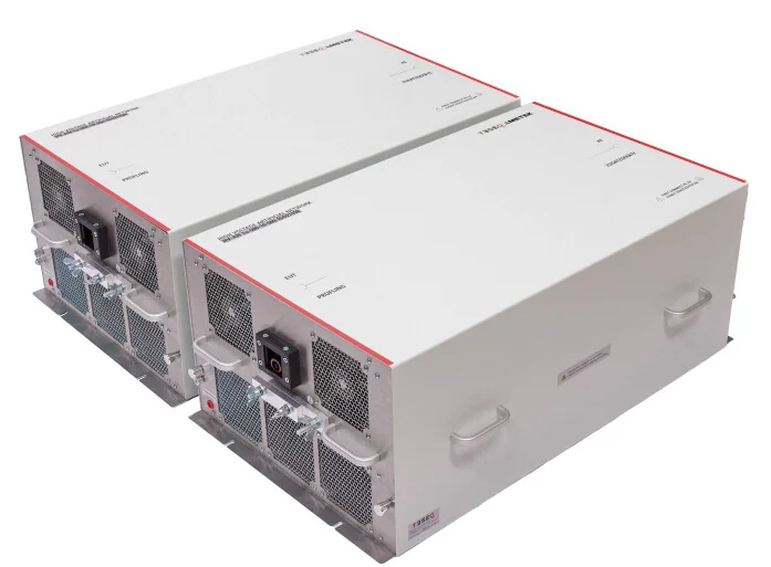
Teseq HV-AN 1u-500 ISO 21498 artificial network modules
Source impedance

HV-AN 1u-500 ISO 21498 set

A pair of 1 microhenry, 1 microfarad modules that give the HV bus the impedance ISO 21498-2 draws, tuned as a set.

  • ISO 21498-2, MBN 11123 and BMW GS 95023
  • 10, 25 or 100 milliohm sets, up to 500 A
  • 1000 V DC, 1500 V DC isolation to ground
  • Air cooled, 51 kg per module, trolley available
EM TEST PowerWave 250 electronic power source
DC source, when needed

PowerWave 250-DC

A bidirectional source for the bus when the laboratory has none. The customer's own supply can take its place.

  • Up to 1500 V DC, fully bidirectional
  • 1250 V per millisecond slew for ISO 21498-2, LV 123, MBN 11123 and VW 80300 dynamics
  • AC and DC in one footprint for ECE R10 charging tests
  • Test library in net.control
The pain point

An amplifier and a transformer on a live 800 V bus is not a ripple test

Assembling a ripple set-up from an audio amplifier, a coupling transformer, a capacitor bank and an oscilloscope leaves the level open-loop and the safety chain to the operator.

Conventional: assembled from separate parts

DC supply, LF amplifier, coupling transformer, capacitor bank, oscilloscope with a current probe and a PC to close the loop by hand.

PC and softwareSignal generatorLF amplifierCoupling transformer OscilloscopeCapacitor bankDC supplyEUT loop closed by hand10 Hz to 300 kHznot rated for HVone ratio, fixed with current probeno discharge circuit800 V, high currentcharger or converter the level is read on the scope and corrected by hand, per point
7boxes around a live bus
0interlock across the chain
1operator closing the loop
  • The ripple level at the EUT drifts with the EUT's impedance and switching noise, and a scope reading cannot separate the ripple from the noise
  • A fixed transformer ratio cannot give both the voltage at low current and the current at high current the standards ask for
  • The capacitor bank holds a lethal charge with no automatic discharge or interlock
  • Every OEM profile is built point by point

Integrated: Ripple NX with the HV-AN 1u-500

Amplifier, coupling network, capacitor bank and measurement share one control unit, one interlock chain and one connection box.

Ripple NX LF amplifier, to 10 kVACoupling, 2:1 and 4:110 mF capacitor bank4-channel measurementControl unit, interlock, discharge, fuses DC sourceown or PowerWave HV-AN 1u-500ISO 21498-2 network EUTcharger or converter Impedance mode, calibration mode, then a list of test points
1system, plus the network
1interlock chain, source to EUT
0points corrected by hand
  • Frequency-selective channels measure the ripple at the EUT terminals and regulate it, even on a bus full of switching noise
  • The transformer ratio switches automatically between 2:1 for voltage and 4:1 for current
  • The capacitor bank pre-charges and discharges under control, inside the interlock chain, with EUT fuses in the box
  • ISO 21498-2, LV 123, VW 80300 and MBN 11123 run as stored lists, with per-output current and voltage limits
Our strengths · HV ripple

Why we lead with the Ripple NX for HV components

Rated for the bus

Up to 1000 V and 1000 A DC through the coupler, with the connection box and cables sized for traction and charging equipment, not adapted from a bench set-up.

Closed-loop at the terminals

Frequency-selective measurement channels read the ripple where the standard defines it and hold it there, whatever the EUT's impedance does at a resonance.

Safe by design

Interlock circuit, emergency circuit, active and passive discharge of the capacitor bank, high-voltage indicator and EUT fuses are part of the system, not an afterthought.

Two outputs, one test

The 600 A and 1000 A models feed two EUT connectors, so a battery is tested through both axle connectors with individual limits on each.

The impedance the standard draws

The HV-AN 1u-500 set is tuned as a pair to the ISO 21498-2 curve, in 10, 25 or 100 milliohm versions, up to 500 A.

Supported and calibrated here

ICX Lab Services installs the system, trains the team and calibrates the artificial networks on site under the accredited scope.

HV coupling · CISPR 25, IEC 61000-4-4, -4-5, -4-6 on DC ports

Emission and immunity at operating voltage

Standard artificial networks and CDNs are rated for a few hundred volts. These are rated for the bus, so a charger or converter is measured and stressed while it runs at 800 V and full current.

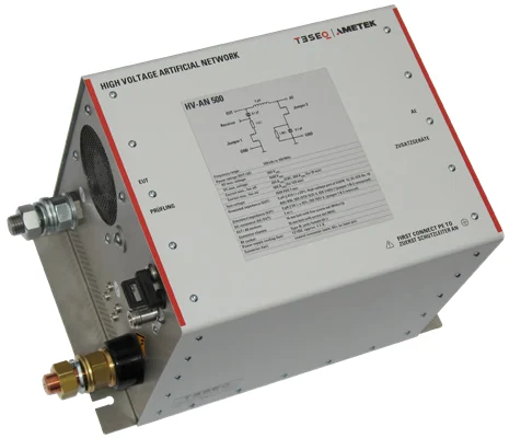
Teseq HV-AN 500 high-voltage artificial network
Star product

HV-AN 500

A 5 microhenry artificial network for 500 A that covers the high-voltage and, with its option, the low-voltage parts of CISPR 25.

  • 100 kHz to 100 MHz
  • 1000 V DC, 500 V AC, 500 A with fan cooling, 200 A passive
  • CISPR 25, CISPR 12, ECE R10, ISO 11452-1, ISO 7637-2, ISO 7637-4
  • DC resistance 1 milliohm
  • About 8.5 kg, M16 bolt terminals
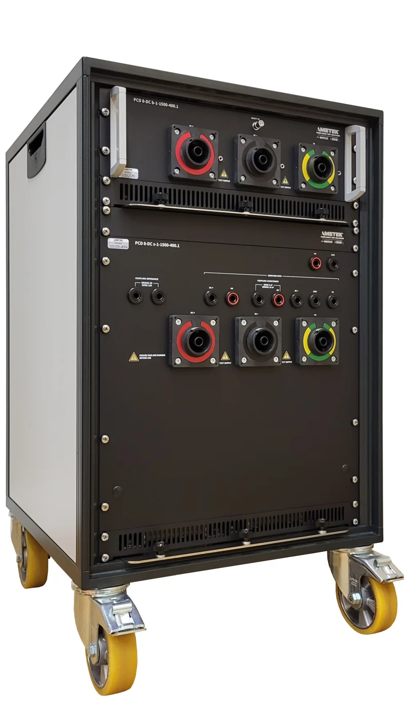
AMETEK CTS PCD 8-DC surge coupling network
Burst and surge coupling

PCD 8-DC series

Surge coupling and decoupling for high-current DC lines, in a rack with room for the matching burst network.

  • 1500 V DC, 63 A to 200 A or 125 A to 400 A
  • Surge to 8 kV, 2 ohm differential and 12 ohm common mode
  • Coupling mode set by jumper: DC+ to DC-, or either or both to PE
  • Driven by the compact NX7 or NSG 3040A and 3060A
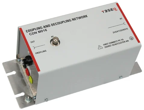
Teseq CDN M series coupling and decoupling network
Conducted RF coupling

CDN M216-1000V and M232-1000V

IEC 61000-4-6 coupling networks for DC+ and DC- rated well above the bus.

  • 1000 V AC, 2000 V DC line to line
  • 16 A or 32 A, 150 kHz to 230 MHz
  • M3 to M5 versions to 1000 V AC for three-phase inputs
  • Driven by the NSG 4070C
EM TEST compact NX7 transient generator
Transient generator

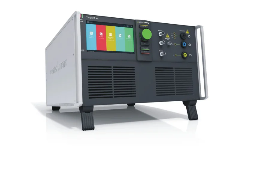
compact NX7

Burst, surge, ring wave and power fail in one 7-inch touch-screen generator that also controls the external coupling networks.

  • Burst 5.5 kV, surge and ring wave 7 kV
  • Built-in single-phase CDN 400 V, 32 A for the AC side
  • Recognises the connected EUT power configuration
  • Monitor outputs for peak voltage and current
The pain point

A 400 V coupling network on an 800 V bus is a derating, not a test

Laboratories that grew up on mains-powered products own networks rated for a few hundred volts. On a high-voltage bus, they are bypassed with adaptors, tested at reduced voltage, or replaced piecemeal from several vendors.

Conventional: mains-rated networks pushed onto the bus

A standard 400 V CDN, an external decoupling filter, a third-party HV coupling box, adaptor leads, and a supply turned down to what the networks tolerate.

Surge generatorSupply turned down Standard CDN3rd-party HV box Adaptor leadsExternal decouplingMains LISNEUT rated for mainsbelow bus voltage 400 V DC ratingno interlock rated by nobodyits own box50 uH, not CISPR 25tested derated the standard CDN cannot sit on the bus, so the test runs at a voltage the product never sees
3vendors in one signal path
1test run below operating voltage
0ratings for the adaptor leads
  • A CDN rated 400 V DC on an 800 V bus is either bypassed or destroyed, so the immunity test is run at a reduced supply
  • A mains LISN's 50 microhenry impedance is not the 5 microhenry network CISPR 25 specifies for vehicle supply lines
  • Third-party HV boxes bring their own connectors, no interlock and no control from the generator
  • Nobody certifies the adaptor leads between the vendors' boxes

Integrated: HV-rated networks driven by the generators that know them

The HV-AN 500 for emission, the PCD 8-DC for burst and surge and the CDN M-1000V for conducted RF, each rated above the bus and each controlled by its AMETEK CTS generator.

EMI receivercompact NX7NSG 4070CEUT on the HV bus quoted separatelyburst and surgeconducted RF800 V, full current HV-AN 500 pairPCD 8-DCCDN M232-1000V 1000 V DC, 500 A1500 V DC, 400 A, 8 kV2000 V DC line to line Every network rated above the bus, every one driven by its own generator
1vendor, generator to network
0tests run below operating voltage
1500V DC surge coupling rating
  • The HV-AN 500 gives the 5 microhenry impedance CISPR 25 defines, at 1000 V DC and 500 A, and the option covers the low-voltage part too
  • The PCD 8-DC couples 8 kV surges onto a 1500 V DC line at up to 400 A, with the coupling mode set by a jumper and the burst network in the same rack
  • The CDN M-1000V series takes 2000 V DC line to line, so conducted RF immunity runs at the operating point
  • The compact NX7 and NSG 4070C drive the networks they were designed with
Our strengths · HV coupling

Why we lead with HV-rated networks from one range

Rated above the bus

1000 V DC for the artificial networks, 1500 V DC for surge coupling and 2000 V DC line to line for conducted RF. Nothing on the bench is the weak point.

One network for both parts of CISPR 25

The HV-AN 500 serves the high-voltage part as standard and the low-voltage part with its 1 microfarad option, so one pair covers the vehicle supply lines.

Full current, not a fraction

500 A through the artificial network, 400 A through the surge coupler. Chargers and inverters are tested at the current they deliver.

The generator knows the network

The compact NX7 recognises the connected supply configuration and offers only the couplings that exist. The PCD 8-DC is on its supported list.

Burst and surge in one rack

The PCD 8-DC surge network has space for the matching burst network in the same housing, so the DC port is wired once for both tests.

Calibrated on site

ICX Lab Services calibrates artificial networks and CDNs in your laboratory under the accredited scope, so the HV bench never leaves the building.

Test coverage

HV DC tests these two systems perform

Ratings are those published in the EM TEST and Teseq datasheets. The DC source can be the customer's own supply or a PowerWave 250-DC. DC dips and interruptions to IEC 61000-4-29 are covered by the NetWave series on the AMETEK page.

TestStandardRequirementEquipment
HV ripple
Superimposed AC rippleISO 21498-2, LV 12310 Hz to 300 kHz on buses to 1000 V DC and 1000 ARipple NX with connection box
OEM ripple profilesVW 80300, MBN 11123, BMW GS 95023Stored test lists with per-output limitsRipple NX
Source impedance for ripple and emissionISO 21498-21 microhenry, 1 microfarad, 10 to 100 milliohmHV-AN 1u-500 ISO 21498 set
Bus voltage dynamicsISO 21498-2, LV 123, VW 80300Ramps and steps at 1250 V per millisecondPowerWave 250-DC, when the customer has no source
HV coupling
Conducted emission, HV supply linesCISPR 25, ECE R10150 kHz to 108 MHz at 1000 V DC and 500 AHV-AN 500 pair with EMI receiver, quoted separately
Conducted emission, LV supply linesCISPR 25Same network with the 1 microfarad optionHV-AN 500 with option
Surge on the DC portIEC 61000-4-5Up to 8 kV on lines to 1500 V DC and 400 Acompact NX7 with PCD 8-DC
Electrical fast transient on the DC portIEC 61000-4-4Up to 5.5 kV on lines to 1500 V DCcompact NX7 with PCD 8-DC burst network
Conducted RF immunity on the DC portIEC 61000-4-63 V to 10 V on lines to 2000 V DC line to lineNSG 4070C with CDN M216-1000V or M232-1000V

Testing on an 800 V bus?

Give us the bus voltage, the current and the specifications your customer cites. We size the ripple generator, the artificial networks and the coupling networks to that bus, and calibrate them on site after delivery. Quotations on request.

Request a quotation   WhatsApp us

Tell us what you need to test

We reply within one working day with a quote or a plan.

Contact us