Electric vehicles and components · ISO 7637, ISO 16750-2, LV 124, LV 148

A component bench built around the battery, not a power supply

An automotive ECU is tested on the supply it will live on: one that dips, ramps, sinks current and carries transients. Two systems cover the electrical tests an OEM asks for. Supply and transients: the VDS 200Q four-quadrant battery simulator with the UCS 200N and LD 200N. Emission and BCI: the NSG 4070C with the CIP 9136A probe, HV-AN 150 networks and the AES 5501.

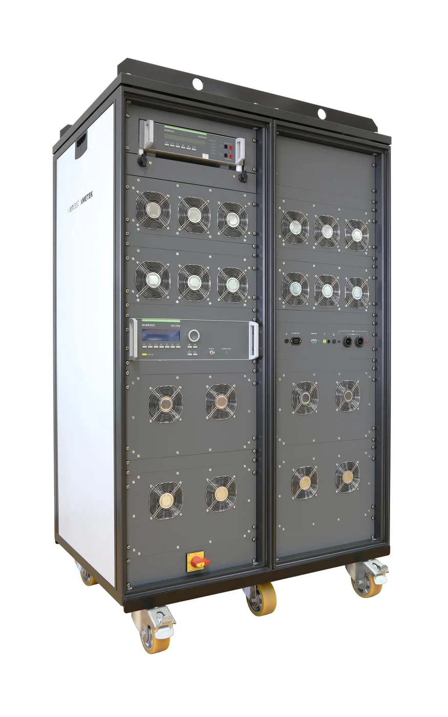
EM TEST VDS 200Q four-quadrant battery simulatorVDS 200Q four-quadrant battery simulator, 60 V to 80 V, up to 200 A
Supply and transients · 12 V, 24 V and 48 V

The supply is the instrument

The VDS 200Q feeds the component under test with the voltage profile of the standard and absorbs whatever the component sends back. The UCS 200N and LD 200N put the ISO 7637-2 and ISO 16750-2 pulses on the same line through their own coupling networks.

EM TEST VDS 200Q series battery simulator rack
Star product

VDS 200Q series

Four-quadrant bipolar amplifier that simulates the battery and sinks energy fed back by the DUT, with the lowest source impedance in its class.

  • Minus 20 V to plus 80 V, 10 A to 200 A continuous, 600 A peak
  • Source impedance below 10 milliohm, programmable 10 to 200 milliohm on the .2 models
  • Bandwidth DC to 150 kHz at full signal, 250 kHz extended
  • Sense lines for voltage-drop correction at the DUT
  • LV 124, LV 148, ISO 16750-2, ISO 21848, BMW GS, VW 80000 and MBN LV 124-1 profiles, pulses 2b and 4 pre-programmed
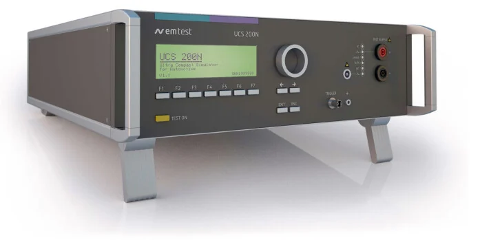
EM TEST UCS 200N ultra compact simulator
ISO 7637-2 pulses 1, 2a, 3a, 3b

UCS 200N series

Burst generator, micropulse generator, coupling network and battery switch in one box.

  • Micropulses 20 V to 600 V, source impedance 2 ohm to 450 ohm
  • Burst 25 V to 1000 V, 5 ns rise, to 200 kHz
  • Built-in coupling network 80 V DC, 50 A to 200 A
  • Its coupling network can be used, and controlled, by the LD 200N for load dump pulses
  • FreeStyle mode for parameters beyond the standard
  • 3U and 25 kg for the 50 A model
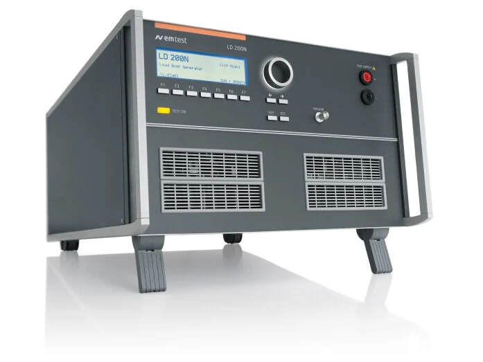
EM TEST LD 200N load dump generator
Load dump, pulses 5a and 5b

LD 200N series

Stand-alone load dump generator with its own 80 V coupler and the clipping circuit the standards call for.

  • 20 V to 200 V, 40 ms to 400 ms pulse width
  • Source impedance 0.5 ohm to 38 ohm in 0.1 ohm steps
  • Clipping voltage 15 V to 99.5 V
  • Built-in coupler 30 A, or 100 A on the LD 200N100
  • ISO 7637-2, ISO 16750-2, SAE J1113, SAE J1455, JASO and OEM pulses
The pain point

One supply line, four generators, and a coupling network for each

Every ISO 7637-2 pulse family wants its own generator and its own way onto the supply line. Assembled from separate boxes, the DUT supply is re-cabled for every pulse.

Conventional: bench supply plus a generator per pulse

A laboratory power supply, separate burst, micropulse and load dump generators, an external coupling network and a switch box, all steered from a PC.

PC and softwareBench power supply Burst generatorMicropulse generatorLoad dump generator Coupling networkBattery switch boxOscilloscopeDUT drivers for every boxone quadrant, slow pulse 3a, 3bpulses 1, 2apulses 5a, 5b re-cabled per pulseown controllerto verify each pulseECU or component six control links, and the coupling network re-wired for every pulse family
8boxes on the bench
3times the DUT supply is re-cabled
0current sinking on a bench supply
  • A one-quadrant bench supply cannot absorb the current an inductive load or a regenerating drive returns, so profiles overshoot
  • Bench supplies have source impedances far above the milliohms the standards specify
  • Each generator needs its own coupling network, or the one network is re-cabled per pulse
  • The OEM profile is built by hand in a waveform editor

Integrated: VDS 200Q with UCS 200N and LD 200N

The battery simulator feeds the UCS 200N, whose built-in coupling network carries every pulse family and the load dump to the DUT.

VDS 200Q 4-quadrant amplifierRi below 10 milliohmOEM profile library supplies and sinks UCS 200N BurstMicropulseCoupling network 80 V, up to 200 A, battery switch LD 200Nload dump, using the UCS coupler DUTECU or component One supply line, every pulse on it, one iso.control sequence
3boxes, supply to DUT
1coupling network for all pulses
1test sequence per OEM specification
  • The VDS 200Q sinks up to its nominal current, so dips, ramps and reset profiles stay on shape under any load
  • The UCS 200N coupling network carries burst, micropulses and the load dump from the LD 200N, with no re-cabling
  • OEM sequences run from the iso.control library, with the report written as the test runs
  • Pulse verification uses the supplied calibration adapters on the same bench
Our strengths · Supply and transients

Why we lead with the VDS 200Q for automotive components

It sinks as well as sources

A four-quadrant bipolar amplifier absorbs the energy an inductive load or a regenerating drive returns, up to nominal current. A bench supply cannot, and the profile shows it.

Milliohms, not tenths of an ohm

Source impedance below 10 milliohm, programmable from 10 to 200 milliohm on the .2 models, matches the figure the OEM specification prescribes instead of approximating it.

The profiles are already in it

LV 124, LV 148, ISO 16750-2, ISO 21848 and the BMW, VW and Mercedes specifications are pre-programmed, with pulses 2b and 4 on the front panel.

One coupling network for every pulse

The UCS 200N carries burst, micropulses and the LD 200N load dump through its own 80 V network, so the DUT supply is wired once.

Sized to the component

From 10 A to 200 A continuous in the same family, with matching UCS 200N couplers from 50 A to 200 A, so the bench grows with the laboratory.

Supported and calibrated here

ICX Lab Services installs the bench, trains the team and calibrates the transient generators and networks on site under the accredited scope.

Emission and BCI · CISPR 25, ISO 7637-2, ISO 11452-4

The other half of the component test plan

Conducted emission and bulk current injection use the same bench, the same artificial networks and, for BCI, one instrument that carries the generator, amplifier and power meters.

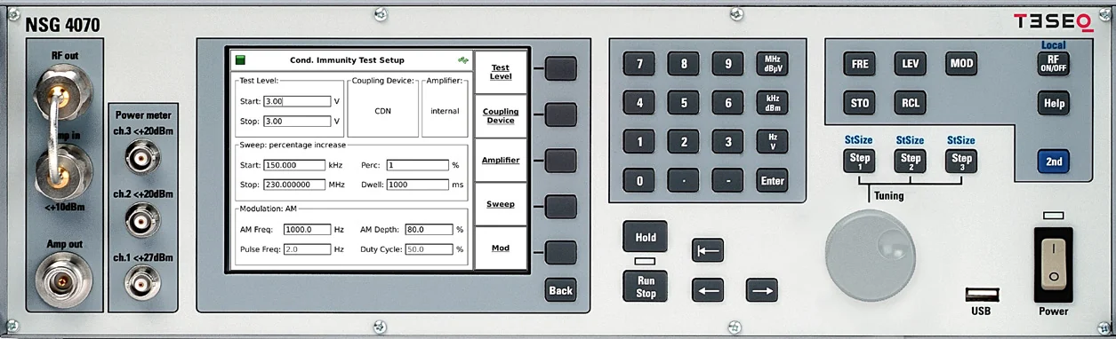
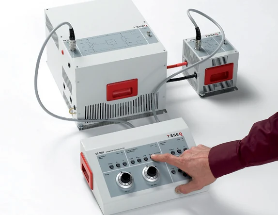
Teseq NSG 4070C conducted immunity test system
Star product

NSG 4070C

Generator, class A amplifier, directional coupler and three power meters in one unit, run from its own menu.

  • Generator and power meters 4 kHz to 1 GHz
  • Internal amplifier options to 110 W, 10 kHz to 400 MHz
  • ISO 11452-4, MIL-STD-461 CS114 and the Ford, GM, Nissan, PSA and Renault BCI methods
  • EUT monitoring inputs, optical remote control
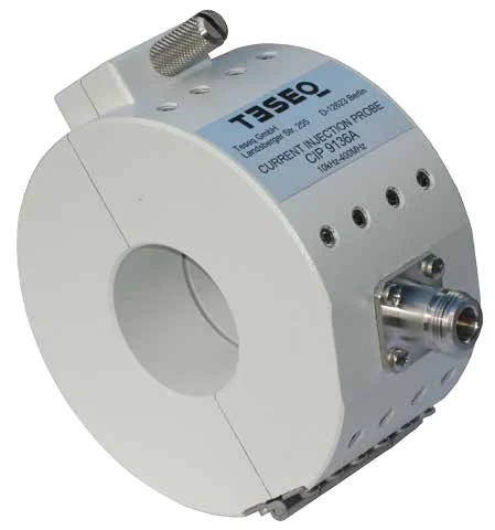
Teseq CIP 9136A current injection probe
Injection probe

CIP 9136A

Non-ferrite core probe that holds its characteristics at the powers automotive BCI needs.

  • 4 kHz to 400 MHz
  • Up to 1 kW without the drift of a ferrite core
  • ISO 11452-4, MIL-STD-461 CS114, IEC 61000-4-6
  • Calibrated in the PCJ 9201B jig
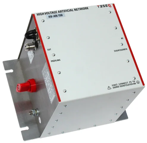
Teseq HV-AN 150 artificial network
Artificial network

HV-AN 150

One 5 microhenry network for the low-voltage and high-voltage parts of CISPR 25.

  • 100 kHz to 100 MHz, usable to 200 MHz
  • 1000 V DC, 500 V AC, 150 A for 60 minutes
  • CISPR 25, CISPR 12, ECE R10, ISO 7637-2, ISO 11452-1, MIL-STD-461, DO-160G
  • DC resistance below 5 milliohm, 4.2 kg
  • SME shielded enclosure for a pair
Teseq AES 5501 automotive emissions system
Transient emission

AES 5501

Electronic switch, mechanical switch, artificial network and control station for ISO 7637-2 emission.

  • 100 A, 0 V to 60 V DC, 300 A inrush
  • Shunt resistors 10, 20, 40 and 120 ohm
  • Internal, external and manual triggering
  • Industry-standard relay footprint, switch counter
The pain point

BCI built from parts is a generator, an amplifier, a coupler, a meter and a laptop

The injection probe is the smallest item on the bench. Everything that drives it and reads it back is where a distributed set-up costs time.

Conventional: assembled from separate instruments

Signal generator, external amplifier, directional coupler, power meter and a PC, each with its own driver, cables and calibration.

PC and softwareSignal generatorExternal amplifierDirectional coupler Power meterMonitor probeInjection probeDUT drivers for every boxto 400 MHzseparate calibrationforward and reverse forward powercurrent, to a meteron the harnessECU and harness control and readback links: one per instrument
7boxes on the bench
5software drivers to keep working
3calibration certificates to track
  • Substitution-method calibration in the jig runs through the PC: step, read, correct, repeat
  • Forward power and injected current come from different instruments and are reconciled in software
  • A ferrite probe warms up at automotive power levels and its insertion loss walks
  • A driver update or a licence lapse stops the test

Integrated: NSG 4070C with the CIP 9136A

Generator, amplifier, coupler and the three power meters share one chassis, one firmware and one calibration.

NSG 4070C Generator110 W amplifierCoupler3 power metersEUT monitoring CIP 9136Aon the harness DUTECU and harness monitor probe back One menu: level, probe, jig calibration, sweep, run
1box, plus probe and jig
0drivers needed to run a test
1calibration for the whole chain
  • Jig calibration and the test run from the front panel, with the calibration file stored in the instrument
  • Forward power and the monitor probe current are read by the same power meters that set the level
  • The CIP 9136A core does not drift with temperature, so the calibration holds through a long sweep
  • The same NSG 4070C runs IEC 61000-4-6 with a CDN for non-automotive products
Our strengths · Emission and BCI

Why we lead with the NSG 4070C and HV-AN 150

BCI without a laptop

The NSG 4070C sets levels, calibrates the probe in the jig, sweeps and stores results on its own screen. Software is an option for automation, never a requirement.

A probe that stays calibrated

The CIP 9136A's non-ferrite core handles up to 1 kW without the temperature drift that moves a ferrite probe's insertion loss during a sweep.

One network for 12 V and 800 V

The HV-AN 150 is rated to 1000 V DC and 150 A, and meets the low-voltage and high-voltage parts of CISPR 25, so the same pair serves the ECU bench and the inverter bench.

Emission switching done properly

The AES 5501 puts the electronic switch, mechanical switch, artificial network and trigger control in one system, with the switch placement ISO 7637-2 and the OEM specifications require.

Shared with the immunity bench

The VDS 200Q supplies the DUT for the emission tests as well, and the HV-AN 150 sits between them, so one bench serves both halves of the test plan.

Calibrated on site

ICX Lab Services calibrates artificial networks, injection probes and jigs in your laboratory under the accredited scope, so they never leave the bench.

Test coverage

Component tests these two systems perform

Levels and ranges are those published in the standards and the EM TEST and Teseq datasheets. Radiated tests in an ALSE chamber and the ISO 10605 ESD test are covered by the NSG 6000A, CBA amplifiers and esd NX30 on the AMETEK page.

TestStandardRequirementEquipment
Supply and transients
Supply voltage profilesISO 16750-2, LV 124, LV 148Ramps, dips, cold crank, reset behaviour, 12 V to 48 VVDS 200Q
Superimposed alternating voltageISO 16750-2, LV 124 E-06Up to 6 V peak to peak, 15 Hz to 30 kHzVDS 200Q
Slow decrease and increase, reversed voltageISO 16750-2Ramps and negative supplyVDS 200Q, minus 20 V to plus 80 V
Transient pulses 1, 2a, 3a, 3bISO 7637-2Micropulses to 600 V, burst to 1000 VUCS 200N, supplied by VDS 200Q
Pulses 2b and 4ISO 7637-2Supply-side transientsVDS 200Q, pre-programmed
Load dump 5a and 5bISO 16750-2Up to 200 V, 40 ms to 400 ms, clipped or unclippedLD 200N through the UCS 200N coupler
Emission and BCI
Bulk current injectionISO 11452-4Up to 200 mA, 1 MHz to 400 MHz, substitution methodNSG 4070C, CIP 9136A, PCJ 9201B jig
Conducted emission, voltage methodCISPR 25150 kHz to 108 MHz, low-voltage and high-voltage supply linesHV-AN 150 pair with EMI receiver, quoted separately
Transient emissionISO 7637-2Slow and fast pulses on the supply line, 100 AAES 5501 with oscilloscope
Conducted RF immunity, non-automotiveIEC 61000-4-63 V and 10 V, 150 kHz to 80 MHzNSG 4070C with CDN

Setting up for an OEM approval?

Tell us which OEM specifications your customer cites and the supply current of the components. We size the VDS 200Q and UCS 200N to that list, add the emission and BCI equipment the plan needs, and calibrate the bench on site after delivery. Quotations on request.

Request a quotation   WhatsApp us

Tell us what you need to test

We reply within one working day with a quote or a plan.

Contact us